148 Results
View results:
Sort by:

Cross-section properties in RFEM and RSTAB include different types of shear areas. This technical article explains the calculation and meaning of various values.
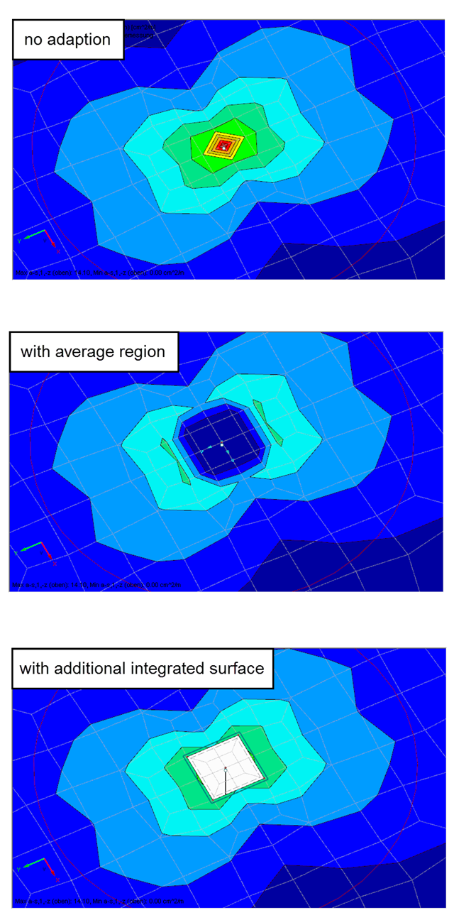
Singularities occur in a limited area due to the concentration of the stress-dependent result values. They are conditioned by the FEA methodology. In theory, the stiffness and/or the stress in an infinite size concentrate on an infinitesimally small area.
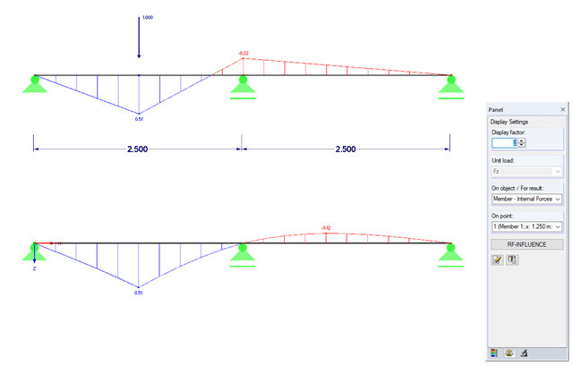
Influence lines are less important nowadays due to fast computer systems. However, it might be an advantage to use influence lines in the phase of preliminary design, as well as in the actual creation of the structural designs. With the RF-INFLUENCE add-on module, influence lines and influence surfaces can be generated and evaluated easily due to a fixed internal force. This technical article describes, with a simple example, the basics of determining and evaluating influence lines.

In accordance with Sec. 6.6.3.1.1 and Sec. 10.14.1.2 of ACI 318-14 and CSA A23.3-14, respectively, RFEM effectively takes into consideration concrete member and surface stiffness reduction for various element types. Available selection types include cracked and uncracked walls, flat plates and slabs, beams, and columns. The multiplier factors available within the program are taken directly from Table 6.6.3.1.1(a) and Table 10.14.1.2.
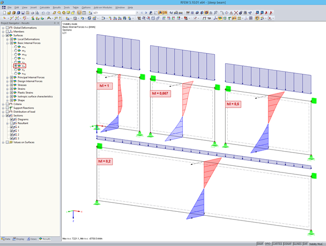
When analyzing structural components of reinforced concrete structures, it is often necessary to design deep beams. These are mainly used for window and door lintels, upstand and downstand beams, the connection between split-level slabs, and frame systems. If they are displayed as surfaces in RFEM, the evaluation of reinforcement results requires further steps.
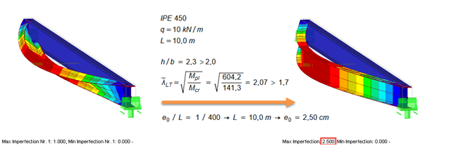
According to EN 1993‑1‑1 [1], it is necessary to use the equivalent geometric imperfections with values that reflect the possible effects of all types of imperfections. EN 1993‑1‑1, Section 5.3, specifies basic imperfections for the global analysis of frames as well as member imperfections.
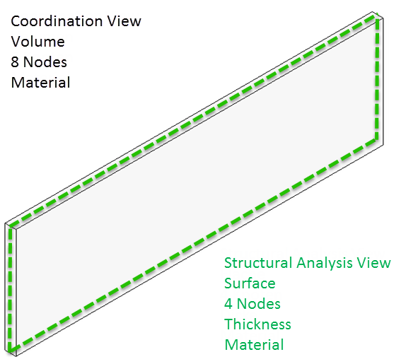
In the BIM workflow, IFC files are frequently used as the basis for data exchange between CAD and structural engineering software. However, there is a fundamental problem with this approach. This article explains various types of IFC files and provides an overview of the import and export options in Dlubal Software programs.
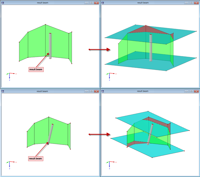
The "Result Beam" member type has been available since the release of RFEM 5. The result beam is a virtual member that does not have any stiffness nor require any support. It can be used in various situations in order to integrate the results from members, surfaces, and solids, and to display them as member internal forces.
Buildings are structures surrounded by wind. The flow around them creates specific loads on the surfaces, which are to be used for the design in structural analysis.

Wind blowing parallel to the surfaces of a structure can generate friction forces on these surfaces. This effect is important mainly for very large structures.
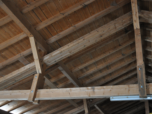
When modeling frame structures, RFEM and RSTAB provide various options for controlling the transfer of internal forces and moments at the connection points of members. You can use the member types to determine whether only forces act on the connected members, or whether moments act on them as well. In addition, you can use hinges to exclude specific internal forces from the transfer. One special form is scissor hinges, which allow for realistic modeling of roof structures, for example.
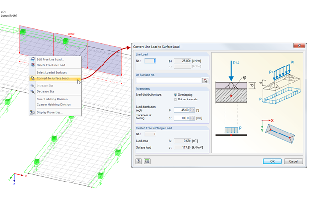
When modeling a load in RFEM, line loads on surfaces are used very often. This may be a line load directly related to a particular load, or a free line load entered at the start and end coordinates.
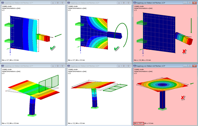
Pay particular attention to the connection points of members and surfaces when you deal with mixed systems, because not all internal forces can always be transferred without difficulty at the coupling location.
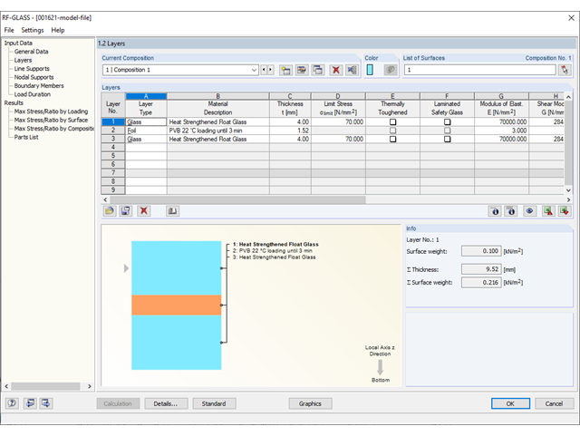
Different glass types and layer structures are available for glass structures used for different purposes. The following types are usually used: float glass, partly tempered glass, and toughened safety glass.

This article describes how a flat slab is generated as a 2D model in RFEM and the loading is applied according to Eurocode 1. The load cases are combined according to Eurocode 0 and calculated linearly. In the RF-CONCRETE Surfaces add-on module, the bending design of the slab is performed while taking into account the standard requirements of Eurocode 2. The reinforcement is complemented by a rebar reinforcement for areas that are not covered by the mesh basic reinforcement.

Reinforced concrete surface design for slabs, plates, and walls is possible in the RF-CONCRETE Surfaces module according to the ACI 318-19 or the CSA A23.3-19 standard. A common approach for slab design is the use of design strips for determining the average one-way internal forces over the width of the strip. This design strip method essentially takes a two-way slab element and applies a simpler one-way approach to determine the required reinforcement needed along the strip length.

In SHAPE-THIN, the calculation of stiffened buckling panels can be performed according to Section 4.5 of EN 1993-1-5. For stiffened buckling panels, the effective surfaces due to local buckling of the single panels in the plate and in the stiffeners, as well as the effective surfaces from the entire panel buckling of the stiffened entire panel, have to be considered.

In RF-STEEL Surfaces, it is possible to display the stresses relevant for the design of welds, for example, according to EN 1993‑1‑8, Figure 4.5. When evaluating the stress components, the local xyz-axis system of the surfaces must be considered.
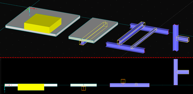
In the case of a parallel offset of the structural plane of members and surfaces and also applying an axial offset to members, for example, the function of eccentricities may be useful.

This article explains the use of surfaces with the Load Transfer stiffness type in RFEM 6. A practical example is also provided to demonstrate the application of self-weight, snow load, and wind load to a steel hall.
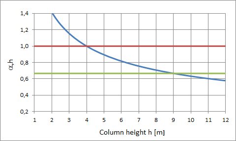
According to EN 1993-1-1 [1], it is necessary to use the equivalent geometric imperfections with values that reflect the possible effects of all types of imperfections. EN 1993-1-1, Section 5.3, specifies basic imperfections for the global analysis of frames as well as member imperfections.

Inserting holes in surfaces is very easy due to the large selection of tools. In order to insert holes or drilling in solids, it is necessary to keep in mind that an opening at the beginning and the end of a continuous hole must be created, as well as a surface that separates the hole from the solids.
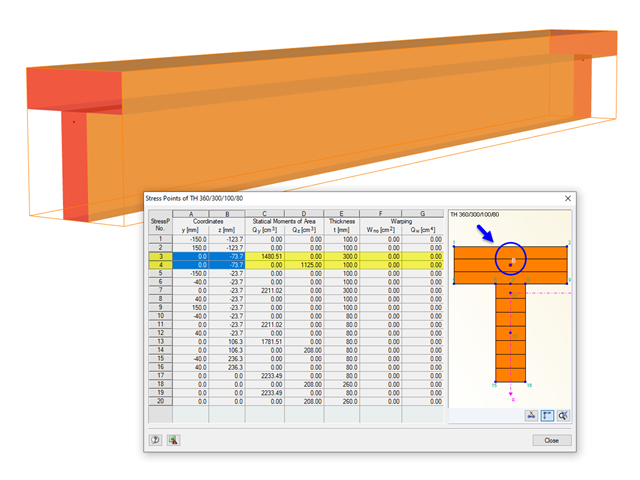
The stresses in the cross‑section of the member are calculated in the stress points. These points are set at locations in the cross‑section where extreme values for the stresses due to the loading types can occur in the material.
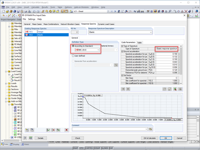
The National Building Code of Canada (NBC) 2015 Article 4.1.8.7 provides a clear procedure for earthquake methods of analysis. The more advanced method, the Dynamic Analysis Procedure in Article 4.1.8.12, should be used for all structure types except those that meet the criteria set forth in 4.1.8.7. The more simplistic method, the Equivalent Static Force Procedure (ESFP) in Article 4.1.8.11, can be used for all other structures.
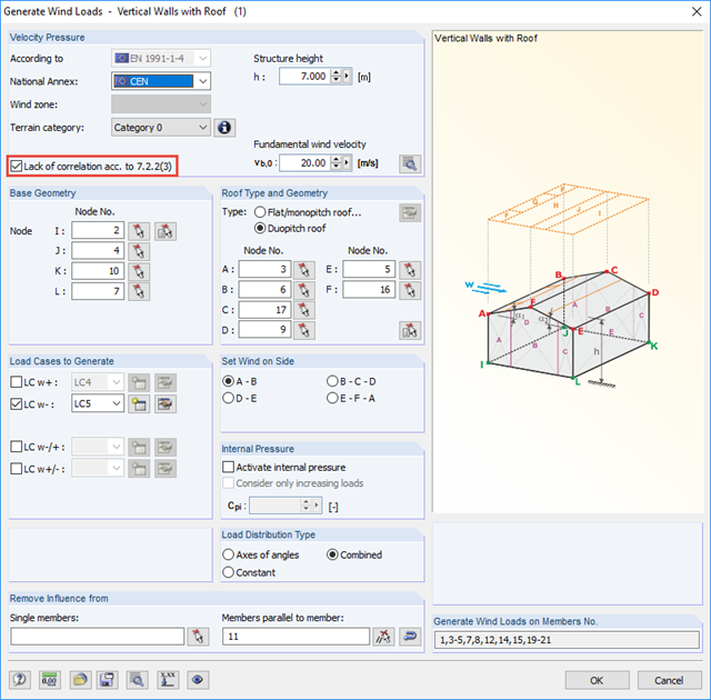
If the wind load for buildings or structures is to be determined by the simultaneous assumption of aerodynamic pressure and suction coefficients on the windward and leeward sides of the building, the correlation of the wind pressure on zones D and E of the wall surfaces may be taken into account.
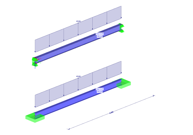
The following example presents a comparison between a shell model and a simple member model performed in RFEM. In the case of the shell model, there is a beam suspended in surfaces, which is modeled with restraints on both sides due to the boundary conditions. This is a statically indeterminate system that forms plastic hinges when overloaded. The comparison is carried out on a member model that has the same boundary conditions as the shell model.
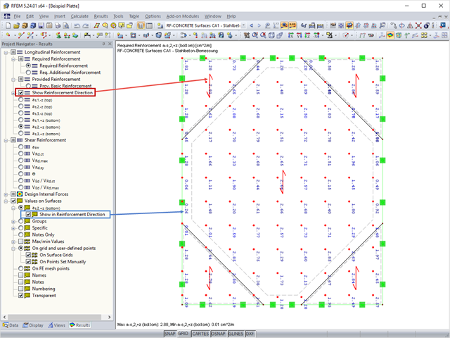
In RF‑CONCRETE Surfaces, the design of the surface reinforcement is done by means of a freely definable reinforcement mesh. In RF‑CONCRETE Surfaces, you can display the reinforcement direction by activating the reinforcement arrow that represents it.
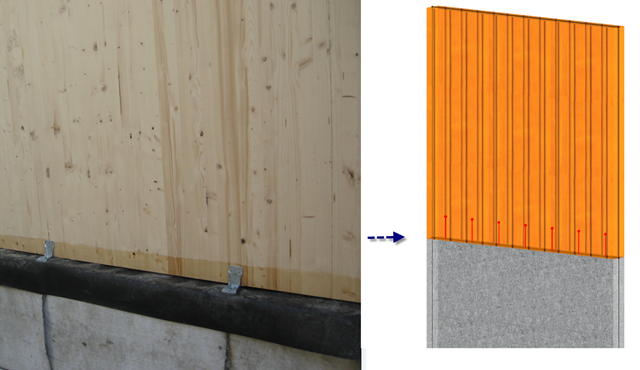
This article deals with considering end releases between surfaces with line hinges and line releases. End releases between surfaces are taken into account using line releases as well as line hinges. The examples are joints in reinforced concrete structures and frame joints in cross-laminated timber structures.

In RFEM, you can display the contact properties between two surfaces by means of contact solids. Among other things, you should ensure that both contact surfaces of a contact solid have the same integrated objects. Therefore, when modeling the contact surfaces, we recommend using the copy function in order to create the second contact surface.

In RFEM and RSTAB, there are various options to renumber the individual structural elements, such as nodes, lines, members, surfaces, or solids. Two options are available for renumbering: singly and automatically.